Installation & Operation Instructions for
EMSPowered In-dash MR2 Side Gauges
Contents of package:
1 x left gauge – fuel / water temp
1 x right gauge – configuration dependant on purchase – purchased as either oil temp / pressure or AFR / EGT or boost / AFR
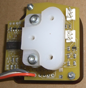
1 x power supply (with 2 screws and doublesided adhesive)
2 x switch with mounting ring
6 x mounting screws
1 x jumper cable
(also included will be sending units for any temperature, pressure or EGT gauges)
The water temp and fuel temp sensors are small straight brass probes that are approximately 2″ long.
The oil pressure sensors are the ones with the “bulb/bulge” at the end with a small threaded section.
The EGT sensors are the ones that come with a long probe and a braided stainless steel sheething.
Notes before installation:
1) Always ground yourself using a static control wrist strap when working on the gauge cluster during installation of the EMSPowered gauges. This will prevent the possibility of damage from static shock. Static shock is especially dangerous in cold/dry climate.
2) When handling the gauge be careful not to scratch the lense. The lense is durable but will scratch if handled improperly.
3) We do not include long lenghts of wire with our gauge because there are so many different ways to wire the unit. Make sure you have enough wire for your installation.
Tools/items needed:
* Philips screwdriver
* Flathead screwdriver
* Drill
* A small cutting tool of some type (razor, exacto knife, serated knife/edge, etc) or a dremel tool with a cutting/sanding head
* Enough wire to connect the guages, sensors and switches
* Electric tape and/or wire insulation
Installation:
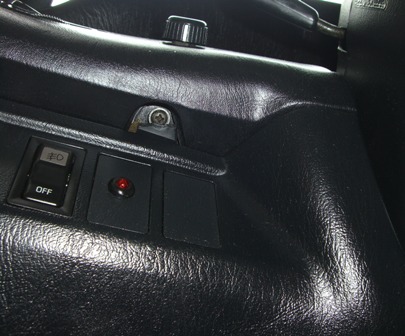
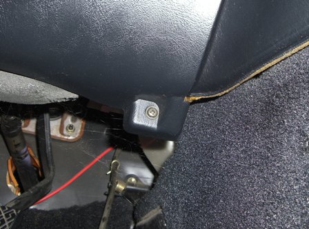
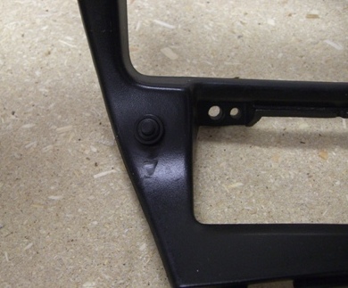
1) Remove the screws holding the plastic trim underneath the steering column. After you remove the screws the piece should snap off with a little bit of pressure. See the following pictures to show the locations of these screws:
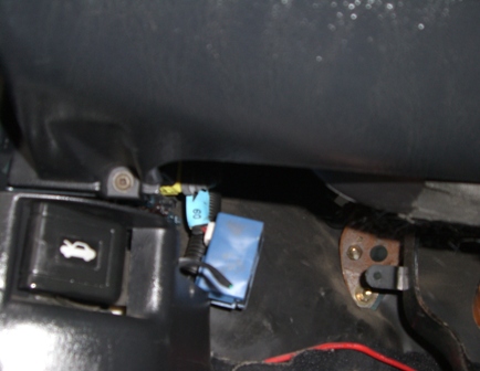
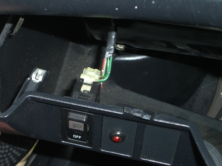
2) When you snap the plastic cover off, you will need to remove the socket connected to your foglight switch (if you have one installed):
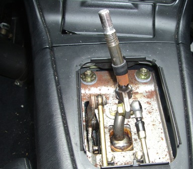
3) Now remove your shift knob by unscrewing it (counterclockwise). After you remove the shift knob remove the leather shift boot by pulling it upwards until it snaps out of place:
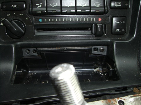
4) Remove your ashtray by pulling it upwards. Now remove the two screws behind the ashtray:
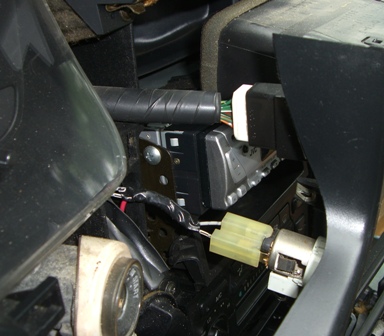
5) Now you can remove the plastic trim surrounging the A/C vents, radio, and A/C controls by pulling gently until it snaps out of place on all corners. You will need to remove the sockets connecting to your cigarette lighter adapter and also your hazard light button:
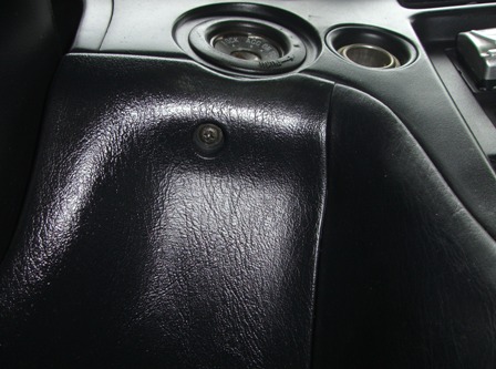
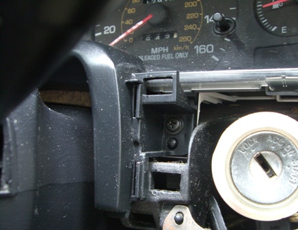
6) Remove the screw directly to the left of the ignition/key tumbler:
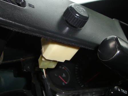
7) Remove the plastic trim piece surrounding the steering column and the far left A/C vent by gently pulling until it snaps out of place. You will need to remove the socket connecting to the dimmer knob:
8) Remove the 3 remaiining screws holding the gauge cluster in place:
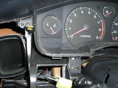
9) Remove the plastic trim piece at the top of the gauge cluster by pulling gently downward until it snaps out of place:
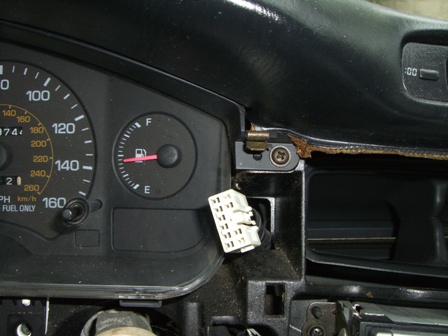
10) This is the most difficult part of the installation. You will need to tilt the gauge cluster forward on one side, reach behind it and remove the cables connected to it in the back. This is easier on 93+ cars with an electrical speedo. On 90-92 cars this is more difficult because of the mechanical speedo which has a cable connected to the back of the gauge cluster which tends to be difficult to remove.
After you remove the cables from the back of the gauge cluster, tilt your steering wheel all the way down and manuver the gauge cluster assembly out. At this point you are ready to get started with the installation of the your new gauges.
11) Take a break, grab a drink, and pat yourself on the back. You are past the most difficult part.
12) Find a clean area that you can work on the gauge cluster. A large table works really well, to allow space to spread your items out without losing anything.
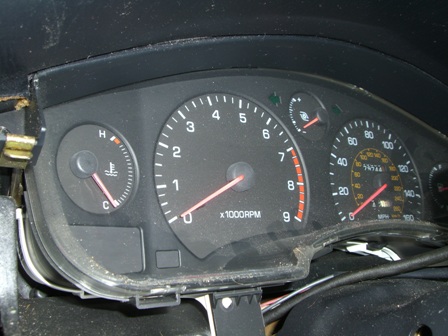
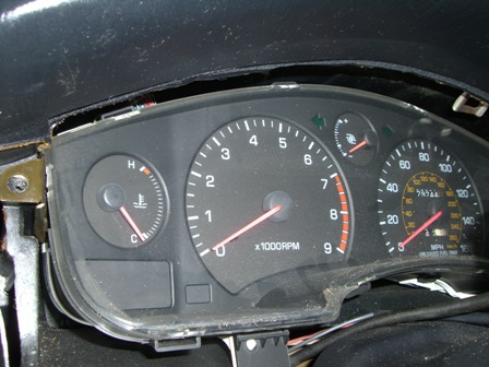
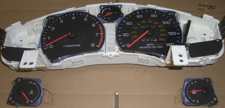
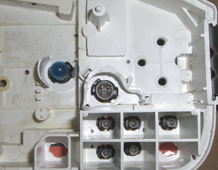
13) Start by removing the front black bezel from the gauge cluster. You do this by undoing the tabs/clips holdling the black bezel to the white housing. You may need a flathead screw driver to pry the tabs loose. After you remove the black bezel your gauge cluster will look like this:

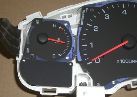
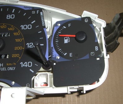
14) Unscrew the 3 screws on holding the OEM fuel level gauge and the 3 screws holding the OEM water temperature gauge (6 screws total). Then remove the two gauges by gently pulling them up and out:

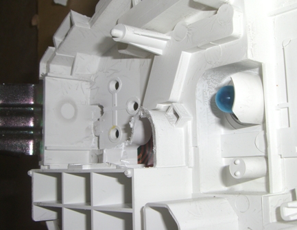
15) Now you will need to cut two small pieces of plastic out of the cluster. There following pictures depict the section that needs to be cut to make room:
BEFORE:


AFTER:

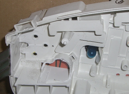

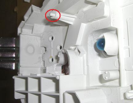
16) Cut the small “nipple” that extends from the standoff on both the left and right side of the gauge cluster. You can see the “nipple” circled in red here:
17) Install both gauges and screw them into place from the back of the gauge cluster using the 6 provided screws. Make sure that you keep all of the wires out of the way so that they don’t bind on anything. This is only a test fitment to make sure that everything fits properly. Check around and under the gauges and make sure that they are sitting properly:


18) Unscrew the gauges from the gauge cluster. Now take the jumper cable with the connectors on either end and connect it from one gauge to the other utilizing the connectors on the back of the gauges (either connector will work, the extra connectors are there for future uses and upgrades). The following pictures show the connectors on the back of the gauges and the jumper cable:

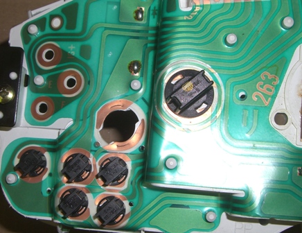
19) Now you will need to figure out how you want to route the wires coming from the gauges out of the gauge cluster. On one side you will notice that there is an unused bulb (which side depends on whether you have a RHD or LHD gauge cluster). You can remove the bulb and use this hole to route the wires from that guage out of the guage cluster. Remove the bulb by grasping it firmly from the back of the gauge cluster, twisting counter clockwise and then gently pulling up and out.

20) For the other side you will need to drill a small 1/4″ hole to route the wires through. Before drilling your hole make sure you look at the back of the gauge cluster to make sure you are not drilling through an electrical trace on the back.
21) After that you have routed your wires through the back of the gauge cluster it is time to mount the gauges back in place using the 6 provided screws. As before, make sure that you are careful not to bind any of the wires while mounting the gauges.
22) Now you will need to decide where you want to mount the programming switches. Most people will mount it next to the dimmer knob or in one of the blank plates where the foglight switch is. Using a 3/8″ drill bit, drill a hole in the location you’d like to mount the switch. Then push the switch assembly through the hole and mount it using the mounting ring provided with the switch. Make sure not to overtighten the ring. Make sure to note which switch is for the left gauge and which switch is for the right gauge. In this picture the switch is mounted to the center trim piece next to the ashtray:
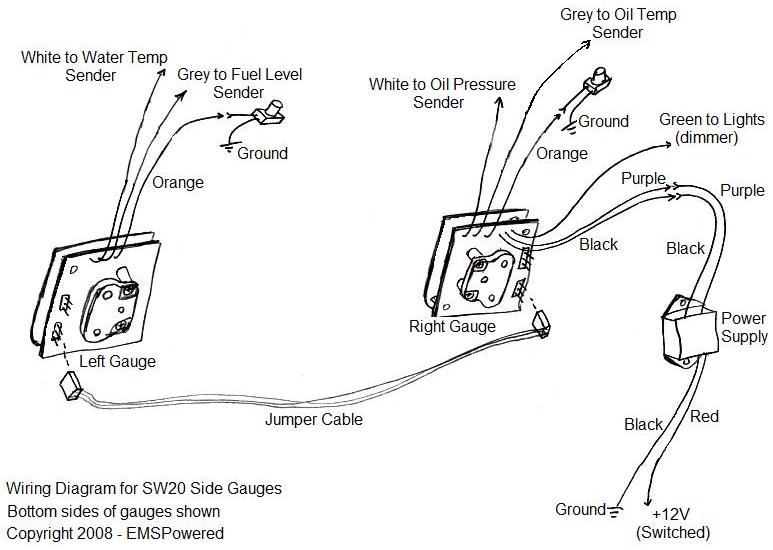
23) Now you will need to connect the wires. Use the following as a guidline:
Wires from the left gauge (fuel and water temperature):
* White –> water temperature sender/sensor
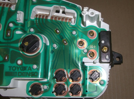
* Grey –> fuel level sender/sensor. The fuel level sensor wire can be connected to the trace labeled “F” on the back of the gauge cluster. You will find this trace on the same side that you removed your OEM fuel gauge from. It will be the lowermost of the 3 screws that held your OEM fuel gauge onto the cluster as shown in the picture above. On some clusters the letter “F” may not be directly printed on the cluster, but the same trace is still the fuel level sender signal.
* Orange –> to one of the wires coming from the switch for the left gauge (either wire will work)
Wires from the right gauge (only if you have the oil pressure and oil temperature gauge):
* White –> oil pressure sender/sensor
* Grey –> oil temperature sender/sensor
* Orange –> to one of the wires coming from the switch for the right gauge (either wire will work)
* Green –> to any switched +12V source to control the nighttime dimmer function (typically wired to headlights or parking lights)
* Purple –> purple wire from the power supply
* Black –> either black wire from the power supply
The following apply if you have the AFR/EGT option for the right side (if you have this option):
* White –> EGT sensor
* Grey –> AFR sensor
Wires from EGT probe (if you have this option):
* Purple or yellow (depending on which EGT probe you have): sensor wire, goes to the white wire from the side gauge
* Black – Ground to chassis
* Red – Connect to switched +12V
Other:
* Red wire from power supply –> to any switched +12V power source (cigarette lighter is a common source)
* Unused black wire from power supply –> to ground (make sure it is a clean ground with any paint scraped off)
* Unused wires from both switches –> to ground (make sure it is a clean ground with any paint scraped off)
WIring diagram (example shown with oil temp/press right side gauge):
24) After you have finished the wiring turn the key to the on position to make sure that the gauges are functioning. Also, make sure that the switches are both functioning per the instructions at the bottom of this page. After you have confirmed this, re-install the gauge cluster along with all of the trim pieces that you previously removed. Make sure to reconnect all of the cables connecting to the back of the gauge cluster.
Congratulations, you’ve installed the all new EMSPowered custom side gauges!
Important notes:
When mounting your oil pressure, oil temperature, and water temperature sensors make sure that they are grounded at the the threads. If you are mounting them into a metal piece on the car in most cases that metal to metal contact will be grounded. If you are mounting them into adapters that don’t have direct metal to metal contact to other parts of the engine that are grounded make sure to run a ground wire to the threaded portion of the sensor. If the sensors are not grounded properly they will not give proper readings.
Operation:
Press and hold the button for a few seconds to change the mode. Press and release quickly (tap the button) to change the setting in any mode. Modes are as follows:
For Fuel Level and Water Temperature Gauge:
| MODE | DISPLAY | SETTINGS |
| Normal | Fuel Level & Water Temp | Standard Display |
| Channel Swap | CH1/CH2 | Allows you to swap the position of the upper and lower displays if desired. CH1 is water temp CH2 is fuel level |
| Low Temp Warning | L1 | Sets the low threshold of the water temp and displays LO if the temp falls below this threshold |
| High Temp Warning | H1 | Sets the high threshold of the water temp and displays HI if the temp goes above this threshold |
| Low Fuel Warning | L2 | Sets the low threshold of the fuel level and displays LO if the fuel level drops below this threshold |
| Brightness Regular | br | Sets the daytime brightness, adjustable from 1 to 9 |
| Brightness Parklights On | bP | Sets the nighttime brightness, adjustable from 1 to 9. Is activated when the “dimmer” (green) wire sees +12V |
| Recalibrate fuel empty | LO | Resets fuel empty parameter. If desired, drain your fuel tank and set this option to recalibrate “empty/ZERO”. |
For Oil Pressure and Oil Temperature Gauge:
| MODE | DISPLAY | SETTINGS |
| Normal | Oil Pressure & Temp | Standard Display |
| Channel Swap | CH1/CH2 | Allows you to swap the position of the upper and lower displays if desired. CH1 is oil pressure CH2 is oil temperature |
| Low Pressure Warning | L1 | Sets the low threshold for oil pressure and displays LO if the pressure falls below this threshold |
| High Pressure Warning | H1 | Sets the high threshold for the oil pressure and displays HI if the pressure rises above this threshold |
| Low Temp Warning | L2 | Sets the low threshold for the oil temperature and displays LO if the temp falls below this threshold |
| High Temp Warning | H2 | Sets the high threshold for the oil temperature and displays HI if the temp rises above this threshold |
| Brightness Regular | br | Sets the daytime brightness, adjustable from 1 to 9 |
| Brightness Parklights On | bP | Sets the nighttime brightness, adjustable from 1 to 9. Is activated when the “dimmer” (green) wire sees +12V |
For EGT and AFR Gauge:
| MODE | DISPLAY | SETTINGS |
| Normal | EGT & AFR | Standard Display |
| Channel Swap | CH1/CH2 | Allows you to swap the position of the upper and lower displays if desired. CH1 is EGT CH2 is AFR |
| Brightness Regular | br | Sets the daytime brightness, adjustable from 1 to 9 |
| Brightness Parklights On | bP | Sets the nighttime brightness, adjustable from 1 to 9. Is activated when the “dimmer” (green) wire sees +12V |
| Empty | not used | This function is here soley for programing functions and cannot be adjusted |


Recent Comments