Installation & Operation Instructions for
EMSPowered MR2 Boost Gauge
Contents of package:
1 x boost gauge
1 x pressure sensor (with 2 screws and doublesided adhesive)
1 x switch with mounting ring
2 x machine screws (to mount boost gauge)
4 x washers/spacers
Notes before installation:
1) Always ground yourself using a static control wrist strap when working on the gauge cluster during installation of the EMSPowered gauge. This will prevent the possibility of damage from static shock. Static shock is especially dangerous in cold/dry climate.
2) When handling the gauge be careful not to scratch the lense. The lense is durable but will easily scratch if handled improperly.
3) We do not include long lenghts of wire with our gauge because there are so many different ways to wire the unit.
Tools/items needed:
* Philips screwdriver
* Flathead screwdriver
* Drill
* 1/4″ drillbit
* 3/8″ drillbit
* Enough wire to connect the guage, pressure sensor and switch
* Electric tape and/or wire insulation
Installation:
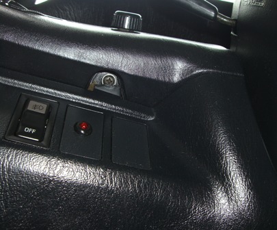
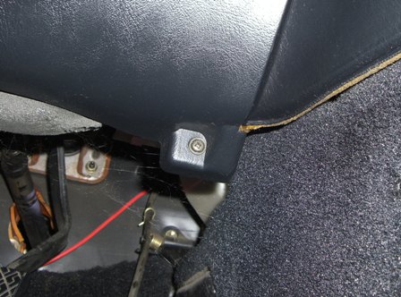
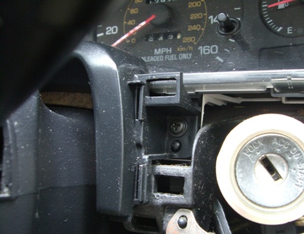
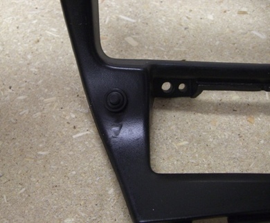
1) Remove the screws holding the plastic trim underneath the steering column. After you remove the screws the piece should snap off with a little bit of pressure. See the following pictures to show the locations of these screws:
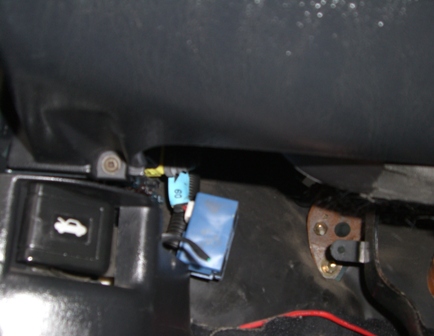
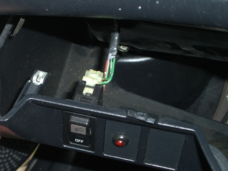
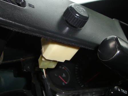
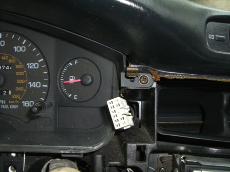
2) When you snap the plastic cover off, you will need to remove the socket connected to your foglight switch (if you have one installed):
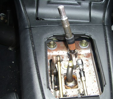
3) Now remove your shift knob by unscrewing it (counterclockwise). After you remove the shift knob remove the leather shift boot by pulling it upwards until it snaps out of place:
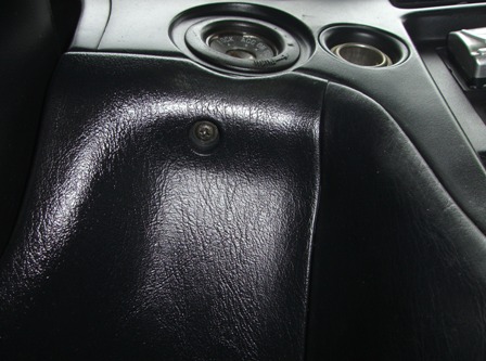
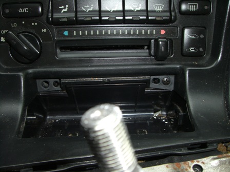
4) Remove your ashtray by pulling it upwards. Now remove the two screws behind the ashtray:
5) Now you can remove the plastic trim surrounging the A/C vents, radio, and A/C controls by pulling gently until it snaps out of place on all corners. You will need to remove the sockets connecting to your cigarette lighter adapter and also your hazard light button:
6) Remove the screw directly to the left of the ignition/key tumbler:
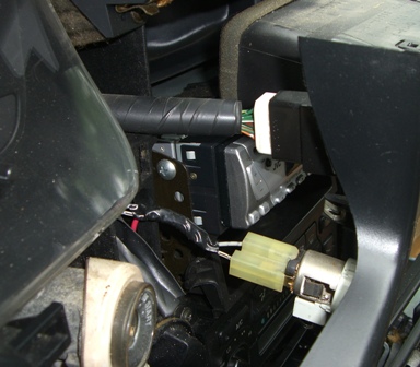
7) Remove the plastic trim piece surrounding the steering column and the far left A/C vent by gently pulling until it snaps out of place. You will need to remove the socket connecting to the dimmer knob:
8) Remove the 3 remaiining screws holding the gauge cluster in place:
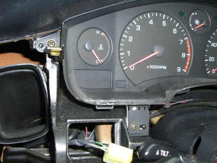
9) Remove the plastic trim piece at the top of the gauge cluster by pulling gently downward until it snaps out of place:
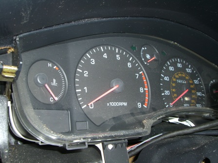
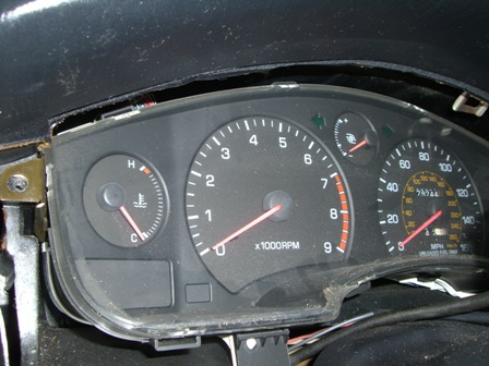
10) This is the most difficult part of the installation. You will need to tilt the gauge cluster forward on one side, reach behind it and remove the cables connected to it in the back. This is easier on 93+ cars with an electrical speedo. On 90-92 cars this is more difficult because of the mechanical speedo which has a cable connected to the back of the gauge cluster which tends to be difficult to remove.
After you remove the cables from the back of the gauge cluster, tilt your steering wheel all the way down and manuver the gauge cluster assembly out. At this point you are ready to get started with the installation of the new gauge.
11) Take a break, get a soda, and pat yourself on the back. You are past the most difficult part.
12) Find a clean area that you can work on the gauge cluster. A large table works really well, to allow space to spread your items out without losing anything.
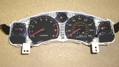
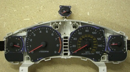
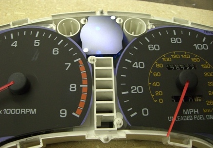
13) Start by removing the front black bezel from the gauge cluster. You do this by undoing the tabs/clips holdling the black bezel to the white housing. You may need a flathead screw driver to pry the tabs loose. After you remove the black bezel your gauge cluster will look like this:
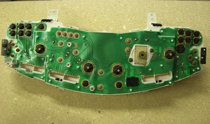
14) Remove the two screws holding the stock Toyota boost gauge (or voltage gauge) in place on the back of the gauge cluster:
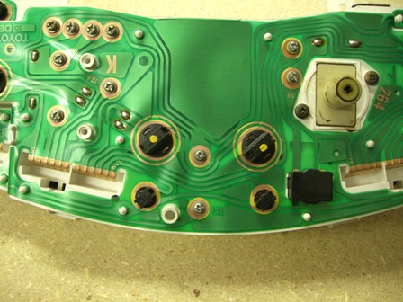
15) After removing the screws, pull up gently on the stock Toyota boost gauge and remove it from the cluster:
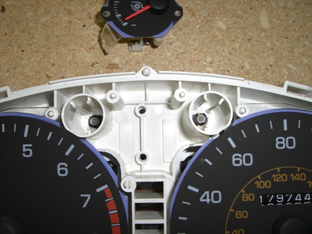
16) Using a 1/4″ drill bit, drill a hole in the spot shown in the picture below:
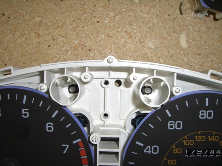
17) Remove your boost gauge from the protective plastic bag. Carefully put each of the wires through the hole you drilled in the previous step. After you get all of the wires through mount the gauge to the cluster using the two screws provided. After you mount the gauge, clip the black bezel back onto the gauge cluster to make sure the gauge sits flush against the bezel. If there is a small gap, you will need to use the provided washers to space the gauge upwards to sit flush with the black bezel. This is due to variation in the gauge clusters. Your Mounted gauge should look like the following before assembling the gauge cluster back together:
18) Now you will need to decide where you want to mount the programming switch. Most people will mount it next to the dimmer knob. Using a 3/8″ drill bit drill a hole in the location you’d like to mount the switch. Then push the switch assembly through the hole and mount it using the mounting ring provided with the switch. Make sure not to overtighten the ring. In this picture the switch is mounted to the center trim piece next to the ashtray:
19) Now you’ll need to mount your pressure sensor in your engine bay. You can mount it anywhere you have space using either the provided mounting screws or the double sided mounting adhesive. If you use the adhesive make very sure that the surface is clean and free of dirt and residue. Now use a small length of vacuum hose to connect from a pressure source to the pressure sensor. A pressure source after the throttle body is preferable to get the most accurate reading.
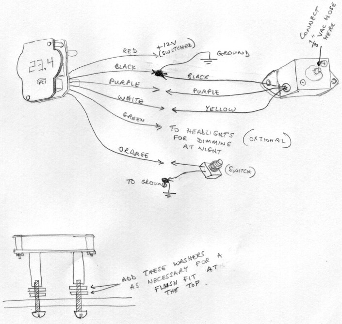
20) Now you will need to connect the wires. Use the following as a guidline:
Wires from the gauge:
* Red –> +12V switched power source
* Black –> black wire from the pressure sensor, and also connect to ground
* Purple –> purple wire from the pressure sensor
* White –> yellow wire from the pressure sensor
* Green –> connect to headlights switch for dimming/nighttime feature to function (optional)
* Orange –> connect to one of the wires coming from the switch (either wire will work)
Connect the other unused wire from the switch to ground. If you use a chassis ground make sure you chean the surface of residue/paint so that you get a solid connection.
21) After you have finished the wiring turn the key to the on position to make sure that the gauge is functioning. Also, make sure that the switch is functioning. After you have confirmed this re-install the gauge cluster along with all of the trim pieces that you previously removed. Make sure to reconnect all of the cables connecting to the back of the gauge cluster.
Congratulations, you’ve installed the all new EMSPowered custom boost gauge!
Operation:
The Vacuum & Boost Gauge will show positive numbers for boost pressure, and negative numbers for vacuum. Press and hold the button for a few seconds to change the mode. Press and release quickly (tap the button) to change the setting in any mode. Modes are as follows:
| MODE | DISPLAY | SETTINGS |
| Normal | Vac / Boost | Tap the button during this normal display mode to display (flash) the peak boost level achieved. Both the numeric and bargraph peaks will be reset |
| Set Bargraph Scale | (this feature is disabled) | (this feature is for future gauges and disabled on this gauge) |
| Peak Mode | (this feature is disabled) | (this feature is for future gauges and disabled on this gauge) |
| Numeric Peak Time | Pt.1 | Sets how long the peak value will be flased on the display from ~1 to 5 seconds |
| Boost Resolution | r.1.0 | Sets the numeric display resolution to 1.0 PSI, 0.5 PSI or 0.1 PSI. This does not affect bargraph resolution/scale |
| Startup Test | (this feature is disabled) | (this feature is for future gauges and disabled on this gauge) |
| Brightness Regular | Br. 9 | Last digit shows regular brightness level from 1 to 9 |
| Brightness Parklights On | BP.1 | Last digit shows brightness level with lights on from 1 to 9 |
Note: Some features are disabled in the firmware, as they do not apply to this particular gauge, but will be used in future releases of other custom gauges.
RESETTING THE AMBIENT REFERENCE
To be able to provide positive (boost) and negative (vacuum) pressure measurements, the boost gauge needs to know the ambient air pressure level. Although this is set at the factory, the ambient pressure may be different at the usage location, or in different climates. You will notice the effects of this as a non-zero reading when the engine is off and the pressure in the intake manifold or vacuum line has had enough time to bleed back to ambient. This reference pressure level can be reset (re-calibrated) by using the following procedure:
* Turn the engine off, and the ignition key off so that the gauge is powered off.
* Allow some time for the pressure in the manifold to bleed off, or temporarily disconnect the vacuum line to the boost gauge.
* Press and hold the button on the front of the vacuum-boost gauge.
* Turn the ignition key on (do not start the vehicle).
* The display should read “End”.
* You can release the switch now.
* Turn the key off.
* The reference level has been re-calibrated. Remember to re-connect the vacuum line if you disconnected it for this procedure


Recent Comments